
Atomic Force Microscopy Tips and Tricks
Last Edit: 21 Jan 2017 | AFM Scihacks ManualsSome tips and tricks to help with AC (Tapping) mode on an Asylum MFP-3D AFM.
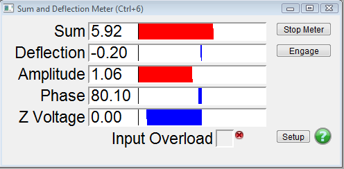
Quick guide to how AC mode works
Shown here are the effects of changing parameters or moving over a sample feature. This is under normal running conditions with no adjustments to the head height.
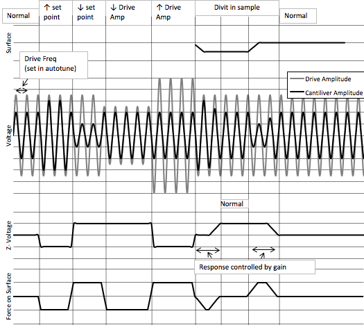
Voltage - measured oscillation (vibration) of the tip.
Z-Voltage (ZV) - voltage applied to the piezo adjusting tip height,↑V = away from sample.
Drive Frequency (DF)- tip oscillation frequency.
- Set Point (SP) - Voltage maintained by adjusting the z-voltage (surface force)
- (damping the oscillation). ↓ Set Point ↑ Force on surface
- Drive amplitude (DA) - is the voltage applied to oscillate the tip.
- Works opposite of Set point. ↑ Drive Amp ↑ Force on surface
Gain - response time of the z-voltage. Too high = ringing and too low = no trace.
Phase - the difference between the input and output signals.
Save Time - Make an experiment file (.pxp)…
It saves your workspace, settings, and save location (yes, you can change it!)
Don’t select a mode on start up; just open your experiment file…
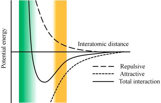
Tuning Parameters
| Repulsive mode | Attractive mode |
|---|---|
| Closer to surface (~1Å) - sharper images - faster tip/sample wear | For ‘Soft’ Samples - often dominated by static charges |
| Use Higher Free Air Amp (1V) | Use Lower Free Air Amp (0.3V) |
| Image at < ‘free air’ phase | Image at > ‘free air’ phase |
| Low Q | High Q |
| Smaller tip radius (shap tip needed) | Larger tip radius |
| Set -8% (left of Resonance) | Set +10% (right of Resonance) |

 Form NPTEL courses
Max Band Width (Max Scan Rate)
Sample Speed must be < Collection Limit to achieve quality scans.
- If not:
- Add increments of -0.005 to the Qgain
- Then “One Tune” – Recalc CL
Phase Hopping (red-blue…)
Or tip not tracing well
- Increasing the DA may help (doubling will often stabilize the phase):
- Just jump up the DA or;
- Save the tip by; Withdrawing the tip → doing the increase → Re-engage - Try up to 4x
Gain will need to be decreased to account for increase in DA
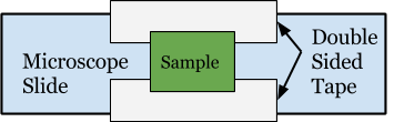
Mounting Your Sample
Reduces drift - Fewer but better contacts - Lower chance of air bubbles - Makes removal easier
Imaging Panels
Height - Corrected Z-piezo voltage (tip height found by feedback loop) - true surface height data
Phase - Phase lag between the drive signal and the detected signal
Z-Sensor - Linear detector of Z height much more accurate than height for features above 1μm but not as good below
Amplitude - Deflection or angle of the tip (not real height of surface)
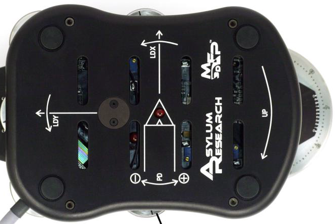
Finding the Laser
Center LDX and Y (8 “turns” from ends)
Laser will be on tip within 1 turn
Turn = :Finger on side opposite of rotation direction :Rotate until finger hits other side ≈180°
Deflection
As Shown turn the PD nob:
:Toward the back of the head to make the deflection more negative
:Toward the front to make more positive
DO NOT EVER force the PD nob - it can cause serious damage!

Save your tip!!!
Load It Properly and Let It Equilibrate!!
- Load tip as shown to the below
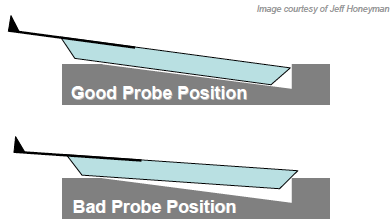
- Load sample and place head (take care not to crash tip!)
- Align laser spot toward end of cantilever and zero deflection

- Do “Auto Tune”, -8% fo
- Check achievable scan rate
- Let sit for 10+ mins (equilibrate)
- Re-zero Deflection
- Do “Auto Tune”, -8% fo
- Check achievable scan rate
- Soft Engage
Save your tip!!! - Soft Engage!
- Perform an Auto Tune
- Set the Set Point voltage to 950 mV
- Click ‘Engage’ button
- Slowly turn the front thumbwheel CCW (Lowering the head)
- Monitor the amplitude voltage (S&D meter)
- Wait for it to equal the Set Point voltage
- This is a false engagement (Engaging water layer…) * Lower the head until ZV is about 40V (halfway blue)
- You’ll notice the ZV seems to float/drift as you move the thumbwheel- that’s because it’s falsely engaged!
- With the radio button for the Set Point voltage activated use the ‘Hamster’ wheel on front of controller to increase the force
- The ZV will move to some more positive voltage value (more red)
- At some point you’ll notice the ZV will no longer quickly become more positive (It may still slowly get more positive)
- At this point, the tip is ‘hard’ engaged on the surface
- Using the thumb wheel adjust the ZV to ≈50V to achieve 70V after reengage
- Withdraw or increase set point to pop tip of surface and lower door
Save your tip!!! - Adjust Gain!
- Increase until you see ringing
- Decrease to get ringing to go away
- Saves tip by optimizing the gain, minimizing the chance that the tip will crash into a large feature
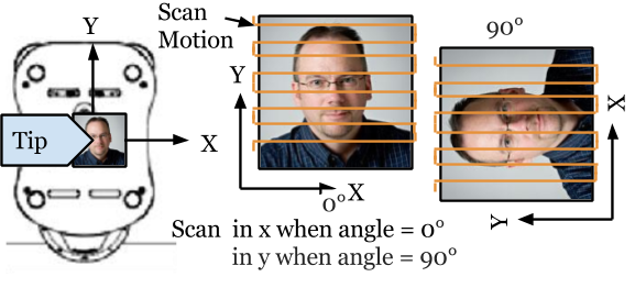
Tip Motion
Tip can be moved from -40 μm to +40 μm or do an 80 μm scan max
Comments